Auer focuses on the manufacture of one-way valves, and carefully improves the quality of each one-way valve. And its sealing performance is one of the important indicators reflecting the quality of performance. In the mass production process, it is very necessary to determine the sealing performance of the one-way valve more quickly and accurately.
For this purpose, Auer has designed an automatic detection device for the tightness of hydraulic check valves, which can more accurately detect the leakage of hydraulic check valves, and intelligently judge whether the detected hydraulic check valves are qualified products.
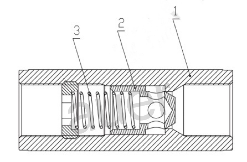
The hydraulic check valve is usually composed of a check valve body, a check valve seat and a spring, as shown in Figure 1. It is widely used in construction machinery, agricultural machinery reversing valves and distributors, and the oil circuit is changed in one direction through the check valve. Especially when the vertical double-acting hydraulic cylinder is used in construction machinery and agricultural machinery, it not only provides kinetic energy to the vertical double-acting hydraulic cylinder through the one-way valve, but also through the matching of the one-way valve body and the one-way valve seat. A one-way sealing effect is formed, so that the internal fluid can only move in one direction. In the operation of the vertical double-acting hydraulic cylinder, when the reversing valve is in the neutral position, that is, during the pressure holding process, a hydraulic control check valve is added to the oil circuit. The oil in the inner cavity, at this time, the piston cannot move due to external force, preventing the hydraulic cylinder piston and slider and other moving parts from sliding down, so that the oil circuit can maintain pressure for a long time.

1. Check valve seat; 2. Check valve body; 3. Spring.
Figure 1 Check valve structure
1 Necessity of one-way valve tightness test
In the process of manufacturing the one-way valve body and the one-way valve seat, due to the coaxiality of the cone surface and the guide cylindricity, the shape processing deviation of the sealing cone surface and the processing quality of the surface finish, the one-way valve body and the one-way valve seat are made. The non-matching and non-continuation of the sealing surface of the valve seat make it difficult for the sealing surface to form a closed ring with a certain sealing specific pressure or a sealing surface of a certain width, thus causing the sealing fluid to continuously pass through the tiny gap between the sealing surfaces to form seepage. leaks or leaks.
The poor sealing performance of the one-way valve will cause poor pressure holding effect of the hydraulic system, automatic lowering of the hydraulic cylinder, loud piston rod retraction noise, and high-frequency or low-frequency vibration during the downward movement of the hydraulic cylinder, which will affect the performance of the hydraulic system. Therefore, in the production process of the one-way valve, how to quickly and accurately test the sealing performance of the one-way valve and determine the qualified product has become the key to ensuring the quality of the one-way valve product.
2 The principle of the one-way valve sealing test and the structure of the detection device
2.1 Principle of check valve seal test
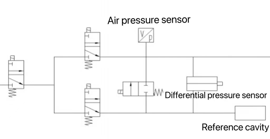
Using compressed air as the measuring medium, in the process of simulating the pressure holding, using the tightness of the one-way valve closed, the oil in the inner cavity of the hydraulic cylinder can be tightly sealed, so that the piston cannot be moved due to external force, and the oil circuit can be long-term. pressure. Through the reference cavity of the one-way valve seal detection device and the one-way valve test tool (including the tested one-way valve), the five states of gas storage, pressure holding, leakage test start, leakage test completion and exhaust completion are carried out. , to measure and determine whether the sealing performance of the one-way valve is qualified, as shown in Figure 2.
2.2 Structure of check valve seal detection device
The structure of the one-way valve seal detection device is mainly composed of the one-way valve test system, the one-way valve
The structure of the valve sealing detection device is composed of a PLC programmable controller. The one-way valve test system consists of air storage tank, pressure regulating valve, 3/2-way solenoid valve, 2/2-way solenoid valve, air pressure sensor, differential pressure sensor, flow sensor, reference cavity and other components.
2.3 Check valve seal detection steps
The gas storage state of the product, simulate the working state of the check valve, design the check valve test tool, the check valve test tool (including the check valve to be tested) and the reference cavity form a detection system, which is input through the PLC programmable controller according to the control panel. The electronic control signal, according to the action set by the program, controls the solenoid valve to open, stores the gas in the two subsystems of the one-way valve test tool and the reference chamber, and the detection system enters the product storage tool and the reference chamber to dynamically monitor the air pressure of the two subsystems. The data is fed back to the PLC control system; the air pressure of the two subsystems reaches the calibration value of the air pressure sensor, the solenoid valve is closed, and the two subsystems of the one-way valve test tool and the reference cavity enter the product pressure holding state.
In the starting state of product measurement, in the pressure-holding state, if there is leakage or leakage in the one-way valve under test, the two subsystems of the one-way valve test tool and the reference cavity will be unbalanced, and the two subsystems will generate a pressure difference. A differential pressure sensor is installed between the two subsystems of the valve test fixture and the reference cavity, and the leakage of the one-way valve can be detected, and the detection system enters the product measurement start state.
When the product measurement is completed, within the specified time, the differential pressure sensor will generate a pressure difference through the two subsystems of the one-way valve test tool and the reference cavity to complete the leakage of the one-way valve, and judge according to the calibration value of the differential pressure leakage value. Whether the one-way valve being measured is a qualified part.
When the product is exhausted, after the product measurement is completed, the PLC control system controls the solenoid valve to send out the gases of the two subsystems of the one-way valve test tool and the reference cavity.
3 Design of the one-way valve seal test tool
3.1 Design principle of one-way valve sealing test tool
When the one-way valve is in the pressure-holding state, the one-way valve body and the one-way valve seat are sealed and matched by the spring expansion and compression force to form a sealing band, which can tightly seal the oil in the hydraulic cylinder cavity. At this time, the fluid cannot be reversed. Movement, the piston can not be moved due to external force, preventing the hydraulic cylinder piston and slider and other movable parts from sliding down.
According to the working principle of the one-way valve in the pressure-holding state, the one-way valve positioning seat is constructed according to the fluid channel structure of the one-way valve parent valve block to ensure that the one-way valve is in the same working state as the parent valve block in the one-way valve positioning seat; The conical plug compresses the check valve to ensure that the spring expansion pressing force is consistent with the actual working pressing force, so that the one-way valve body and the one-way valve seat are in a sealed fit.
3.2 The structure of the one-way valve seal test fixture
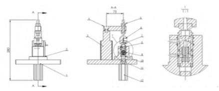
The one-way valve sealing test tool is mainly composed of a fixed floor, a one-way valve positioning seat, a rotary clamping cylinder, a conical plug, a product plug and a cylinder, as shown in Figure 3.

1. Fixed floor; 2. Check valve positioning seat; 3. Rotary clamping cylinder; 4. Cylinder arm; 5. Nut; 6. Compression screw; 7. Conical plug; 8. O-ring;9 . Check valve; 10. Gasket; 11. Product head; 12. Cylinder.
Figure 3 The structure of the one-way valve seal test fixture
3.3 Working steps of the one-way valve seal test tool
When the one-way valve sealing test tool is working, according to the electric control signal input from the control panel, the PLC programmable controller completes the clamping and loosening of the tool and pushes out the tested one-way valve according to the actions set by the program, as shown in Figure 4. .
Check valve seal test fixture clamping, PLC controls the rotation of the clamping cylinder to work, through the rotation of the rotary clamping cylinder, the check valve is compressed with a conical plug, and the check valve spring expansion and compression force is guaranteed to match the actual work. When the pressing force is the same, the one-way valve enters the pressure-holding state.
The one-way valve sealing test tool is loosened. After the one-way valve sealing detection device completes the five states of gas storage, pressure maintenance, leakage test start, leakage test completion and exhaust completion, the PLC controls the rotary clamping cylinder to pressurize. Tightly loosen and rotate to the initial position.
When the check valve is pushed out, rotate the clamping cylinder to press and release, and after rotating to the initial position, the cylinder is controlled by PLC, and the product plug is used to push the check valve out of the check valve positioning seat.

Figure 4 Schematic diagram of the check valve seal test fixture
4 Design of PLC control interface and design of debugging parameters
4.1 Design of PLC control interface
The main PLC control interface is divided into three parts, namely the “Status Monitoring” part on the left side of the interface, the “Test Information” part on the right side of the interface, and the “Process Information and Equipment Running Status and Alarm Information” part at the bottom of the interface。
(1) Status monitoring part. The photoelectric switch is used to monitor and prompt the detection system product gas storage status, product pressure maintenance status, product test start status, product test completion status and product exhaust completion status.
(2) Test information part. Through the feedback of the data information of the air pressure sensor, differential pressure sensor and flow sensor, the real-time values of air pressure and hydraulic pressure can be monitored intuitively, and the air pressure pressure drop value and differential pressure leakage value in the equilibrium stage during the test process can be clearly reflected.
(3) Process information and equipment operation status and alarm information part. Through "equipment normal", "emergency stop is pressed, start failure", "detection photoelectricity is not all sensed, start failure", "depression cylinder depressing timeout", depressing cylinder recovery timeout", discharge cylinder topping timeout"" Various types of information during the operation of the system are prompted, such as "overtime of discharge cylinder return drop", "pressure drop over the upper limit in balance stage", "test differential pressure leakage value over limit" and "reset completed".
4.2 Design of debugging parameters
The debugging parameter setting is divided into three parts: "input and output signal", "use of magnetic cylinder attached" and "test judgment parameter". The "input and output signal" section can monitor the detection of photoelectricity, the control of all cylinders and valves, the three-color lights and the data collection of all sensors; the "cylinder magnetization" section can set and monitor the attachment of the two cylinders. Magnetic use or not; in the "Test Judgment Parameters" section, set the inflation time, balance time, test time, exhaust time, upper limit of balance air pressure drop, upper limit of differential pressure leakage value, and return delay of discharge cylinder.
5 Conclusion
The hydraulic one-way valve sealing detection device adopts PLC programmable controller to automatically control the detection device to operate, which greatly shortens the detection cycle, avoids tedious processing before and after detection, and reduces labor intensity; through the differential pressure sensor Use, convert the differential pressure signal into an electrical signal, can more accurately detect the leakage of the hydraulic check valve, and intelligently judge whether the detected hydraulic check valve is a qualified product. In the test process, compressed air is used as the detection medium, which reduces the test cost and reduces the environmental pollution.