1 Introduction
The OFF R&D team used the dynamic mesh technology in the FLUENT software to numerically simulate the closing process of the one-way valve, and obtained the closing speed of the valve core, the total closing time and the pressure before and after the valve core under the action of different spring stiffness coefficients. bad situation.
The one-way valve is mainly composed of springs, valve cores and sealing ports. When the upstream pressure is higher than a certain value of the downstream pressure, the valve opens; when the downstream pressure is higher than a certain value of the upstream pressure, the valve closes. According to the characteristics that the one-way valve only allows the fluid medium to flow in one direction, it has been widely used in petroleum, chemical, nuclear, hydropower and other industries. At the same time, when the fluid flows through the valve core, the interaction problem with the valve core is the problem of fluid-structure coupling vibration. During the opening or closing process, the flow field around the valve core changes drastically, and the resulting water hammer pressure cannot be ignored. This problem has attracted the interest of many scholars, which has made the design and application of the one-way valve extremely effective. big development.
The R&D personnel of OFF have dynamically simulated the opening process of the one-way valve with different spring stiffness coefficients, and obtained the displacement and movement law of the valve core during the opening process. According to the relevant theory of nonlinear spring mass system, the mathematical model of gas medium check valve is established, the resonance phenomenon of check valve inflation is analyzed, and the flow field distribution of different valves under different opening degrees is obtained. The relationship between the spring stiffness coefficient and the pre-tightening force is studied when the check valve is used as a distribution valve, and the movement curve of the spool when the check valve is opened is obtained. We use the experimental method to study the sealing performance of the one-way valve when it is closed, and obtain that the spring stiffness coefficient is an important factor affecting the creep deformation of the one-way valve sealing cone seat. When the one-way valve is closed, the reverse leakage rate is required to be small, the closing speed should be moderate, the reliability when closed is high, and there is no vibration, shock or noise. The one-way valve has no vibration, shock or noise. It is an important performance of the one-way valve. one of the requirements. One of the main factors affecting the performance of the one-way valve is the spring stiffness of the one-way valve. When the spring stiffness is unreasonably designed, it may cause the one-way valve to surge and close lag. Based on this, this paper uses the dynamic mesh technology of Fluent software to simulate the closing process of the check valve with different spring stiffness coefficients, and the results can provide the basis for the spring stiffness design of the check valve.
2 Establishment of one-way valve model
2.1 Geometric model of the one-way valve flow channel
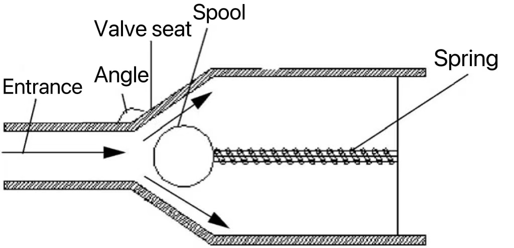
The basic structure of the check valve is shown in Figure 1(a). When the fluid flows through the one-way valve, the flow channel is axisymmetric. In order to reduce the computational workload, the flow channel is simplified into a two-dimensional symmetrical model, and the model is divided into two parts: the grid moving area and the grid static area. Docking is performed by establishing an interface, as shown in Figure 1(b). The main structural dimensions of the check valve are shown in Table 1.
(a)(b)
Figure 1 One-way valve model
Table 1 Main structural dimensions of check valve
Check valve structure geometry
Inlet diameter (mm) 10
Inlet pipe length (mm) 80
Spool movement length (mm) 10
Spool radius (mm) 15
Outlet diameter (mm) 20
Outlet pipe length (mm) 200
Seat length (mm) 16.8
Seat angle (°) 45
2.2 Meshing
A quadrilateral unstructured mesh is used for discretization, as shown in Figure 2. During the closing process, the position of the valve core is moving, and the dynamic grid calculation must be used for simulation. Therefore, the fluid area is divided into two parts, namely the grid changing area and the grid static area. The right side of the dividing line is the grid change area, and the rest area is the static area.
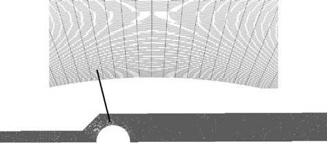
Figure 2 Runner grid
2.3 Fluid calculation assumptions and boundary conditions
Regardless of the compressibility of the fluid in the tube, a Newtonian fluid is assumed. During the closing process of the one-way valve, the velocity at the valve port is relatively large, which is a high Reynolds number turbulent flow, so the classical standard k-ε turbulence model is used. The calculation method adopts the simple SIMPLE method and the standard wall function method. During the closing process of the one-way valve, the upstream inlet pressure must be kept constant, the inlet pressure is set to 0.1 MPa, and the outlet pressure is 0. Due to the short closing time, the time step is set to 0.001 s.
2.4 Moving grid technology and spool motion equation
There are three main ways to update the dynamic mesh: spring-based smoothing, dynamic layering and local remeshing [13]. Since the direction of the movement of the one-way valve can be approximately regarded as a linear movement, the dynamic layering method is selected in this paper. At a small opening, the pressure and speed of the front part of the valve core change relatively large, so the mesh of the front part of the valve core must be refined. The conservation equation of the integral form of the scalar over any control volume is:

in the formula
ρ — fluid density
u - the velocity vector of the fluid
ug — velocity vector of the moving mesh
Γ - diffusion coefficient
A - the area vector of the control volume
 —— The source phase of
During the closing process, the movement of the spool is related to the upstream pressure, downstream pressure and spring force, and its motion equation can be expressed as:

In the formula, m——the quality of the valve core
C - damping coefficient
k - spring stiffness
Fn——The transient pressure on the spool, and it changes with the opening of the spool
It is assumed that the spring force in the one-way valve is horizontal force, which is consistent with the hydrodynamic direction of the fluid, and the movement direction of the valve core is a single horizontal direction. When the valve core is opened and closed, the hydraulic force in both cases is proportional to the opening degree x, and the proportional coefficient of the spring is related to the pressure difference between the inlet and outlet.
By Newton's second theorem:

When the set time step dt is small enough, the spool can be considered to be moving at a constant speed within the dt time. Assuming that the velocity of the spool at the current moment is V0 and the position of the spool is S0, the final velocity at the time of dt is V1, and the displacement of the spool is S=S0+V0+dt. The fluid pressure on the spool Fn= the area A of the grid multiplied by the pressure of each grid, and the spring force on the spool is compiled and realized by the udf function.
3 Calculation results and analysis
3.1 Turn off the displacement time relationship
Under the condition of constant installation length, the relationship between stiffness coefficient and spool displacement is obtained by numerical simulation of the cases with stiffness coefficients of 1100, 1000, and 900. It can be seen that with the increase of the spring stiffness coefficient, the time taken for the valve core to reach the valve seat and reach the equilibrium position during the closing process gradually decreases. During the closing process, the spool with a relatively large spring rate will close relatively quickly. Reduce the spring stiffness of the one-way valve within a certain range to prolong the valve closing time.
It can be seen that with the increase of the spring stiffness coefficient, the pressure difference between the inlet and the outlet increases linearly when the check valve is stable. Reasonable selection of the spring stiffness combination of the one-way valve is of great significance to the life of the valve body. During the closing process, the closing speed of the one-way valve should be strictly controlled. This is because the closing speed of the one-way valve is related to the kinetic energy formed by the mass of the one-way valve. If the closing pressure difference is too large, the kinetic energy of the one-way valve at the moment of closing If there is no time to wear it, it will have a collision effect on the valve seat. Since the quality of the one-way valve spool is constant, the greater the speed when the one-way valve is closed, the greater the impact energy of the one-way valve spool on the valve seat, and the greater the failure speed to the one-way valve.
During the closing process, the valve core of the one-way valve is mainly affected by fluid pressure, spring force, steady-state fluid hydrodynamic force, viscous resistance, inertial force and transient fluid dynamic force, etc. The main acting forces are: spring elastic force, steady-state fluid hydrodynamic force, and reach a state of static equilibrium.
3.2 Spool closing speed
It can be seen that the spool of the one-way valve has a large movement at the opening of 0.006 s, the speed reaches the maximum at about 0.006 s, and the opening degree decreases after 0.006 s. Due to the inertia of the fluid, the valve cannot be closed in time, and finally becoming steady.
3.3 Flow field analysis
It can be seen from Figure 6 that when the pressure difference between the inlet and the outlet is constant, the pressure difference between the front and rear of the valve core increases with the increase of the spring stiffness coefficient of the one-way valve under the condition of different spring stiffness coefficients. When the spring stiffness is larger, the speed decreases too fast when closing, resulting in a sudden decrease in the momentum of the spool, the pressure at the front of the spool will increase rapidly, and the fluid continuity in the pipeline will be interrupted, eventually leading to negative pressure at the back end of the spool . By reducing the spring stiffness coefficient of the one-way valve, the negative pressure area at the rear end of the valve core can be effectively reduced. When the one-way valve reaches the vicinity of the valve seat, the jet flow phenomenon will appear behind the valve core, the velocity of the fluid will increase, the pressure will decrease, and the throat effect will occur.
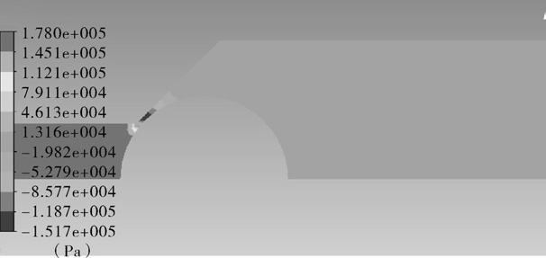
(a) Spring stiffness coefficient 900
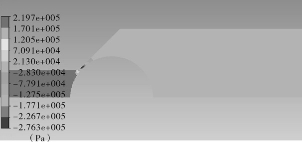
(b) Spring stiffness coefficient 1000
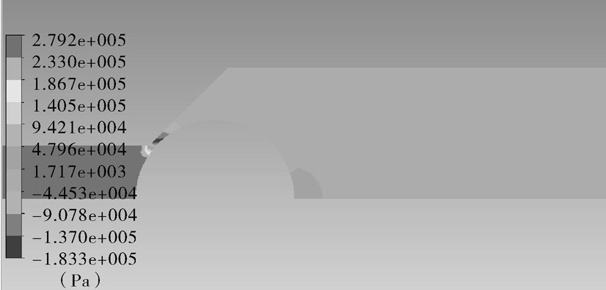
(c) Spring stiffness coefficient 1100
Fig.6 Pressure cloud diagram of one-way valve under different spring stiffness
As the spring stiffness of the one-way valve increases, the closing time is relatively reduced, and the closing speed of the valve is also accelerated, resulting in an increase in the pressure difference between the front and rear of the valve core. The left side of the valve disc is the high pressure area, and the right side is the low pressure area. This time ensures that the valve is always closed. If the one-way valve closes too quickly, the valve is closed before the reverse wave from the inlet reaches the end of the pipe, and the water hammer at the end of the pipe is only affected by the forward wave. This pressure process is called direct water hammer. Before the reverse wave from the inlet reaches the end of the pipe, the valve has not been closed. At this time, the water hammer is formed by the superposition of the forward wave generated at the valve and the reverse wave from the upstream. This pressure process is called indirect water hammer. According to GB/T 20801 ((Pressure Pipeline Specification for Industrial Pipelines), it can be considered safe if the pressure does not exceed 5 MPa. It can be seen from Figure 6 that the one-way valve is in a safe state under the conditions of three different stiffness springs.
3.4 Relationship between spring stiffness and differential pressure
It can be seen from Table 2 that the one-way valve closing process: when the spring stiffness is constant, when the upstream fluid hydrodynamic force on the one-way valve spool is less than the reverse force of the spring, the one-way valve begins to close. When it moves to the left, the spring force it receives gradually decreases, and at the same time, the upstream liquid water force increases gradually. When the spool moves to a certain position, the two forces are balanced, but because the spool still has speed, it will continue to close. , followed by a deceleration exercise. When the spool speed drops to zero, the spool reaches the maximum position, and then accelerates in the opposite direction, reaching a force balance point at a certain moment, and then continues to move to the zero speed point, reaching the minimum position. Then the valve core is accelerated to open under the action of the resultant force, and finally reaches equilibrium after repeated several times. When the one-way valve is in the closed state, the specific pressure of the seal generated by the spring force is small, which is not enough to make the one-way valve tightly sealed, resulting in an increase in the leakage rate of the one-way valve. In addition, ordinary hard-sealed check valves, because the main and auxiliary seals are often made of copper materials, will pollute the water to a certain extent, and once worn or damaged, it is difficult to repair on site, and the flow area is small, and the head loss is relatively small. big. Ordinary soft-sealed one-way valve, although it can reduce the rebound sound and water hammer when it is closed, but the structure is relatively complex, and a valve stem and a spring need to be set. In actual operation, there are often phenomena such as dirt jamming the spring and poor sealing.
Table 2 Differential pressure at full closure at different spring rates
Spring stiffness (N/mm) Pressure before valve (MPa) Pressure after valve (MPa) Differential pressure (MPa)
9000.170.15170.0183
10000.21970.3141-0.0944
11000.46991.292 -0.8221
4 Conclusion
(1) Using the dynamic grid in the FLUENT software to simulate the closing characteristics of the check valve with different spring stiffness, compared with the steady-state simulation, the relationship between the displacement of the valve core when closing, the moving speed and the closing time can be simulated more clearly, The relationship between differential pressure and spring stiffness was determined.
(2) By studying different spring stiffness coefficients, it is concluded that the stiffness coefficient is related to the size of the negative pressure area at the rear end of the valve core.